
KT6368A Bluetooth Chip
KT6368A Bluetooth Chip
Shenzhen Qingyue Electronics Co., Ltd. Product

The KT6368A chip is a pure data chip that supports Bluetooth dual mode and complies with Bluetooth 5.1. The highlights of the chip are its ultra-small size, extremely competitive price, and straightforward passthrough and UART AT control functionalities.
Chinese Name: KT148A Sound Chip
Manufacturer: Shenzhen Qingyue Electronics Co., Ltd.
I. Hardware DescriptionDetails | Parameter Specifications |
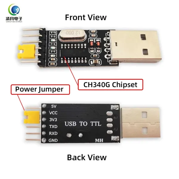
UART Interface | Standard UART interface with TTL level,Baud rate is configurable,A level converter (e.g., CH340G—USB to TTL) is required when connecting to a PC. |
Input Voltage | Recommended voltage: 3.3V (operating range: 2.2V–3.4V). |
Rated Current | Chip startup current: 20mA.Enters low-power mode immediately after startup, alternating between 20µA (broadcasting) and 4mA (wake-up).After a successful connection, the current remains constant at 4mA. |
Low Power Consumption Current | The chip calculates average current because it continuously alternates between low-power mode and wake-up mode internally. |
Operating Temperature | Range: -40°C to 80°C. |
Humidity | Range: 5% to 95%. |
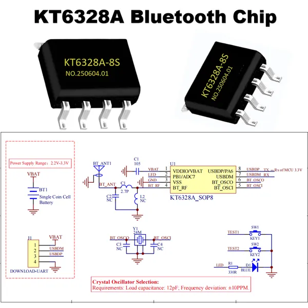
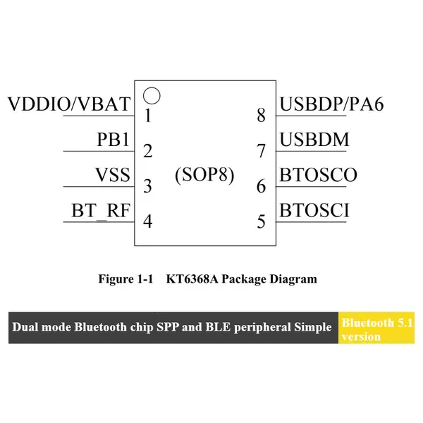
Main Chip Model | KT6368A [SOP8][shipped in tubes],KT6328A [SOP8][shipped in tubes] |
Divided into two versions: KT6368A and KT6328A.
(1) The KT6368A version does not support low power consumption and is a dual-mode version. It consumes 15mA at startup and stabilizes at around 6mA afterward.
(2) The KT6328A version is a low-power version that supports only BLE.
(3) The hardware of these two chip versions is identical.
Step | Instructions |
Step 1 | Set up the peripheral circuit for the chip and supply it with 3.3V power. For the Bluetooth antenna, simply solder a wire in place. |
Step 2 | Check if Pin 2 of the chip outputs a high level for 1 second upon power-on. Connect an indicator light to observe this. |
Step 3 | Connect to a computer using a serial port assistant tool. Verify if the chip’s TX pin returns data at a baud rate of 115200. |
Step 4 | Create your actual board and debug it with the MCU. |
IV. Pin Description
No. | Layout Considerations |
UART Considerations | 1. The internal IO voltage of our chip is 3.3V. 2. When connecting to an external MCU, add series resistors (approximately 100 ohms) to the RX and TX lines. If the MCU’s IO level exceeds 3.3V, increase the resistor value to 1K. 3. Pin 8 of the chip is the TX pin of the KT6368A, which connects to the RX pin of the MCU. Pin 7 is the RX pin of the chip, which connects to the TX pin of the MCU. |
Power Supply Considerations | The maximum supply voltage for the chip is 3.4V. |
Pin 2 Considerations | Pin 2 is the connection status pin. It outputs a high level when connected successfully and remains in a high-impedance state when disconnected. During debugging, it is recommended to connect an indicator light or route it to an external MCU. Ensure a 10K pull-down resistor is connected to ground. |
Detailed Descriptions | 1. Strictly adhere to the recommended supply voltage. There are no significant requirements for the power supply design. 2. For the Bluetooth antenna, follow the provided footprint. The technology is mature, and the communication distance typically exceeds 15 meters. 3. Test points must be reserved for Pins 7 and 8, as they serve as the upgrade interface. This is crucial in case an upgrade is needed. |
 ---- Sourced from Baidu Baike
Recently Posted
-
The KT148A Chip Gives Robot Vacuums a Voice for Worry-Free Whole-Home Cleaning
November 30, 2025In recent years, as living standards improve and work pressure increases, more and more households have begun relying on smart app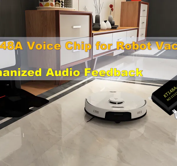 Read More
 -
Application of KT148A Voice Chip in Smart Infusion Monitoring Systems
September 25, 2025Introduction: When Medical Devices Meet Intelligent Voice PromptsIn modern medical environments, infusion therapy is a common trea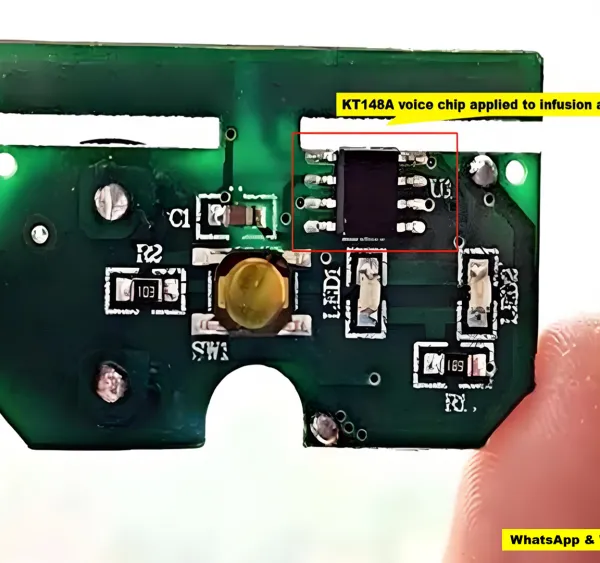 Read More
 -
Understanding BLE (Bluetooth Low Energy) vs. Classic Bluetooth: A Comprehensive Guide
September 16, 2025Bluetooth technology has evolved significantly, powering a wide range of devices from wireless headphones to smart home gadgets. T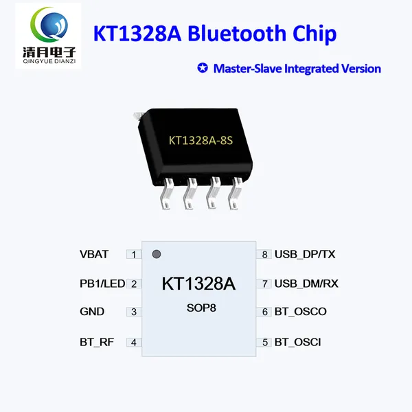 Read More
 -
KT142A - 16S MP3 Decoding Chip: Unleashing a New Intelligent Experience for Children's Electric Toot
September 16, 2025"Brushing teeth is like a battle!" This is the helpless feeling of many parents. Surveys show that over 70% of children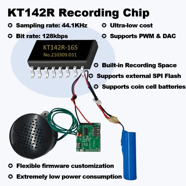 Read More

Contact Us
Recommended Products
-
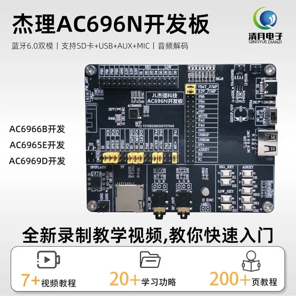
 JL AC6966B AC6965E AC6969D Development Board Kit Open Source SDK Schematic Debug Tool Core Board AC696 Bluetooth SoC Evaluation Test Board for SpeakerUS$ 30MOQ: 1 Piece
 -
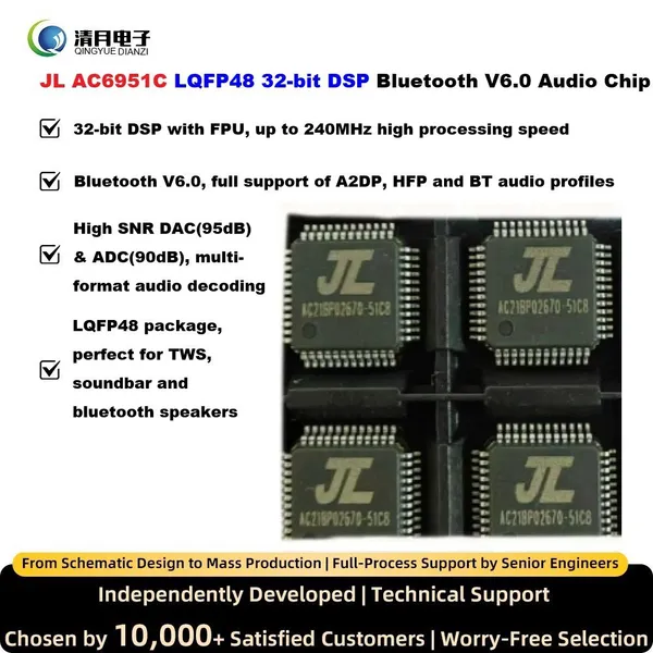
JL AC6951C LQFP48 32-bit DSP Bluetooth V6.0 Audio Chip 240MHz FPU DAC ADC Encoder Decoder For Bluetooth Speaker Soundbar TWS Speaker Alarm Clock AudioUS$ 1MOQ: 1 Piece
-
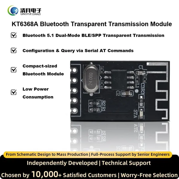
KT6368A Bluetooth Module Support 5.1 BLE/2.1 SPP Transparent Transmission Pure Data IC UART AT Controller For Arduino or ESP32US$ 1MOQ: 1 Piece
-
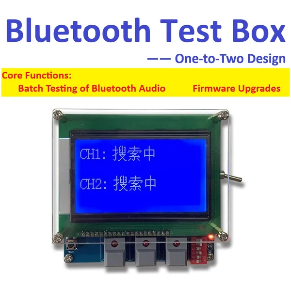
JL Bluetooth Test Box AC692N/AC695N/AC696N Compatible Full Series One-to-Two Testing Batch Upgrade for JieLi Audio Bluetooth Chip Test 9V Power SupplyUS$ 80MOQ: 1 Piece
-
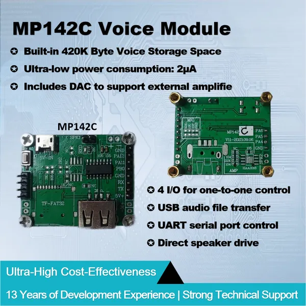
Voice Module MP142C 320KB Built-in Space 4 IO TTL or Serial Port Control PWM Directly Drive Speaker or DAC External Power Amplifier MP3 Sound PlaybackUS$ 2.5MOQ: 1 Piece
-
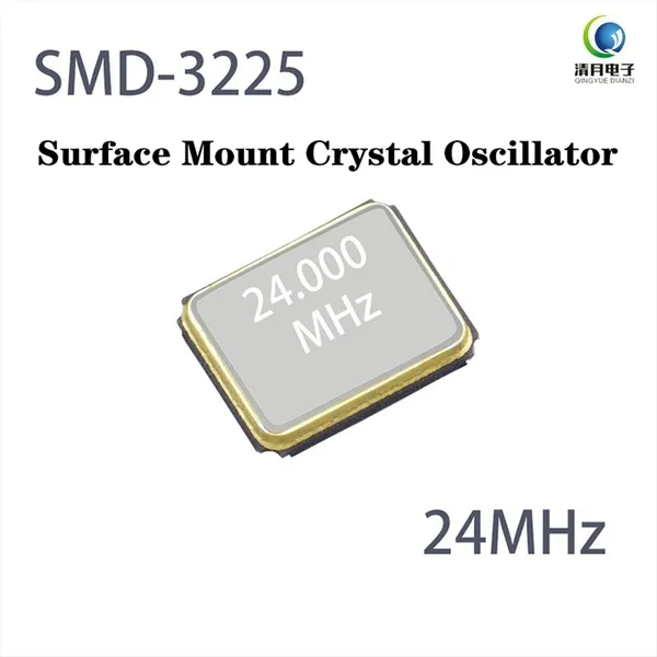
3225 SMD Crystal Oscillator 24.000MHz 12pF 10ppm Matched for JieLi Bluetooth Chip IC JL Bluetooth Audio Module Wireless Device DIY Electronic SMT 4PINUS$ 1MOQ: 1 Piece
-
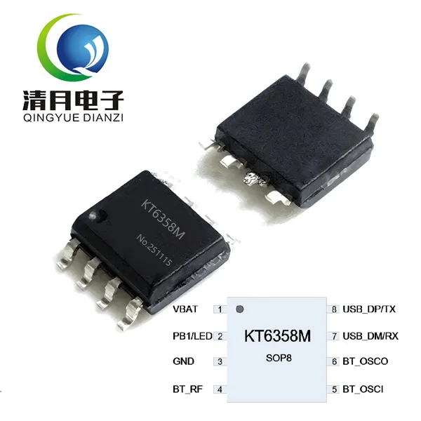
KT6358M BLE Master Bluetooth Chip IC Auto Connect Slave Module Support AT Command UART Control by STM32MCU ESP32 Arduino SOP8 Transparent TransmissionUS$ 1MOQ: 1 Piece
-
USB to TTL CH340G Flash Memory Board Module 3.3V/5V Universal UART Debugging Tool for MCU Arduino Nano Mini Pro ESP32 ESP8266 STC STM32 Raspberry PiUS$ 2MOQ: 1 Piece
-
KT1025B BT301 Bluetooth 5.0 Audio Chip Support U-Disk TF Card SPIFLASH MP3 Decoder BLE SPP UART AT Command Control For Speaker DIY for Audio ReceiverUS$ 1MOQ: 1 Piece
-
M49S Crystal Oscillator SMD Package Surface Mount 24.000MHz 12pF 10ppm High-Precision Mini 2PIN for JieLi Bluetooth Audio Chip JL IC Automotive GradeUS$ 1MOQ: 1 Piece
-
MP142A Voice Module Built-in MP3 Audio Flash Memory External Flash TF Card USB Disk Sound Playback UART AT Control PWM Drive Speaker or DAC AmplifierUS$ 4MOQ: 1 Piece
-
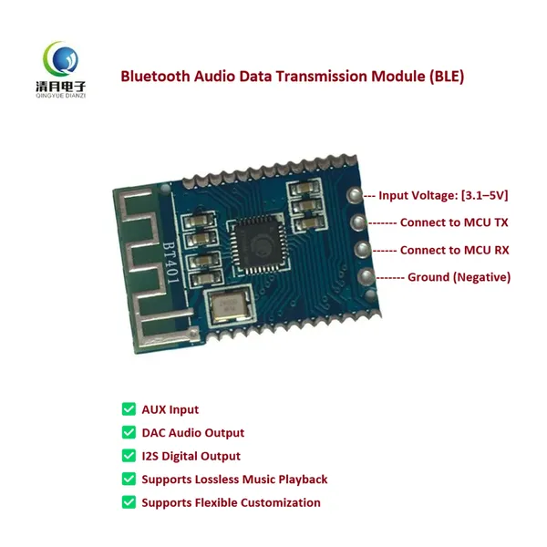
BT401 Dual-Mode Bluetooth Module 5.0 With Built-in Prompt Sound External SPI Flash TF Card USB Audio BLE Data Transmission UART AT Command ControlUS$ 1MOQ: 1 Piece
-
KT6368A Bluetooth HID Dual-Mode BLE and SPP Version Module for Bluetooth Keyboard/Mouse Remote Controller and Selfie Shooter With AT Commands via UARTUS$ 1MOQ: 1 Piece
-
KT1328A Bluetooth Chip Master-Slave Integrated Ver JieLi IC BLE Passthrough Serial Port AT Command Control by Arduino Nano SOP8 for Remote-controlledUS$ 1MOQ: 1 Piece
-
MP404A Micro USB Downloadable MP3/WAV Music Board Play Voice Module Sound Box for Plush Toys Christmas Birthday Creative Greeting Cards DIY Xmas GiftsUS$ 2MOQ: 1 Piece
-
KT142S Voice Chip MP3 Player Module 3 Trigger I/O USB Update 0.5W Speaker Support DAC Output Sound IC for DIY Electronics Gift Christmas Jewel CaseUS$ 1MOQ: 1 Piece
-
10pcs HAA2018 Amplifier IC Small Speaker 4 Ohms 5W Audio Power Amplifier Chip SOP8 Voice Amplifier Circuit Replaces to 8002 Chip for Bluetooth SpeakerUS$ 1MOQ: 1 Piece
-
JL Chips Forced Download Tools 4.0 Updater Full Series JieLi Bluetooth Chips Programmer MCU Development IC Burner USB Serial Port Debug Upgrade DongleUS$ 8MOQ: 1 Piece
-
KT6328A Bluetooth Chip BLE 5.1 Passthrough 20µA Ultra-low Power Consumption Bluetooth IC AIoT Serial Port Data Communicate AT Command Bluetooth ModuleUS$ 1MOQ: 1 Piece
-
KT142R Voice Recording IC Programmable Sound Chip for Toys Stuffed Animals PWM Output Alternative to ISD1820 Low Power Flexible Firmware Bulit-in MemUS$ 1MOQ: 1 Piece